|
PS_Fgen_FW
4da88f4073c1cc65ea45c3a652a2751e495e50db
Firmware for an Power Supply and Function Generator build from an ATX power supply
|
|
PS_Fgen_FW
4da88f4073c1cc65ea45c3a652a2751e495e50db
Firmware for an Power Supply and Function Generator build from an ATX power supply
|
All input and output capabilites are derived from a base class Channel. At the moment there are the following channel types:
POWER_SUPPLY_CHANNEL_TYPEThe power supply channel has settings for the output voltage, enabled state. Also the over voltage protection (OVP), over current protection (OCP) and over power protection (OPP) can be configured. The actual voltage and current is also stored here.
The voltage is regulated to the required value using a software PID regulator. The following picture shows the basic PID block diagram (image from https://rn-wissen.de/wiki/index.php/Regelungstechnik).
An anti-windup scheme is also implemented with the PID integrator part to prevent integrator windup when the output is saturated (based on code from https://www.embeddedrelated.com/showcode/346.php).
The power supply channel supports two different regulation modes:
DDS_CHANNEL_TYPEThe DDS channel has settings for the output amplitude, offset, frequency, enabled state and signal form. It holds the table with all data points that are used by the DDS algorithm for signal creation. The following waveforms are supported: SINE, RECTANGLE, TRIANGLE, SAWTOOTH, DC, USER_SIGNAL.
The user defined signal form can be downloaded to the device for each channel using the SOUR#:FUNC:DAT SCPI command. The user signals for each channel are stored in EEPROM and therefore are available until the next waveform is downloaded and overwriting the last one.
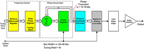
The DDS algorithm is implemented in the DDS.cpp file. Use the Configuration.h file to change the parameters for the DDS algorithm. The following picture shows the basic DDS block diagram including phase truncation (image and more details on https://www.digikey.de/de/articles/the-basics-of-direct-digital-synthesizers-ddss).
DMM_CHANNEL_TYPEThe DMM channel simply holds the measured ADC voltage value of the corresponding DMM input channel.