|
PS_Fgen_FW
4da88f4073c1cc65ea45c3a652a2751e495e50db
Firmware for an Power Supply and Function Generator build from an ATX power supply
|
|
PS_Fgen_FW
4da88f4073c1cc65ea45c3a652a2751e495e50db
Firmware for an Power Supply and Function Generator build from an ATX power supply
|
The user interface is made up of the following components:
All user inputs are directly enqueued into an RingBuffer when they occur. They are then later processed by the main loop. This approach is used to decouple the user input producers (ISRs) from the processing itself (which could take some time). The following user inputs are detected:
The user interface is based on a self developed UI library (https://github.com/M1S2/UI_Lib).
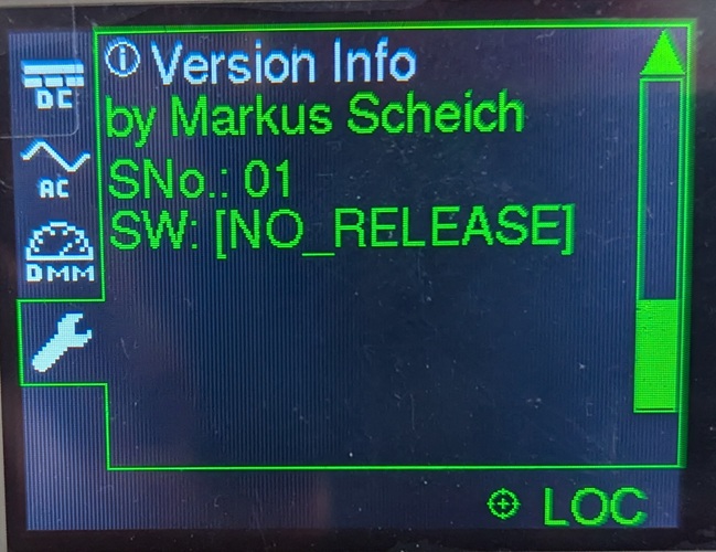
Welcome screen that shows the project name, the serial number of the device and the software version number.

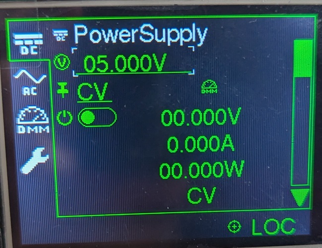
User interface part for the power supply channel of the device.
This screen can be used to change the power supply voltage settings. Also the output can be enabled or disabled and there is a control for the regulation mode. Also the actual measurements (voltage, current, power) are shown.
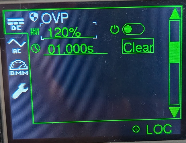
Settings for the over voltage protection of the power supply channel (protection level in % of the configured output voltage, Enabled/Disabled state, protection delay after which the protection kicks in, button to clear an active protection)
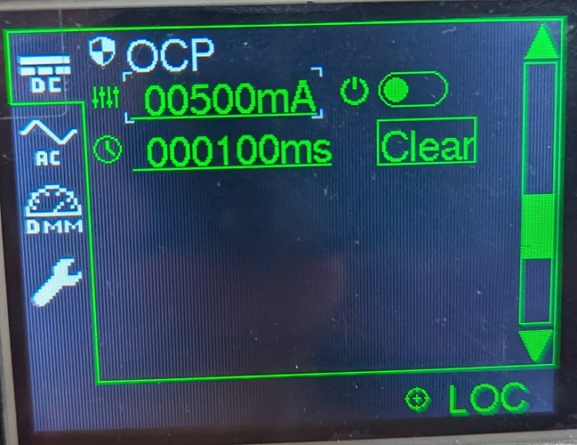
Settings for the over current protection of the power supply channel (protection level in A, Enabled/Disabled state, protection delay after which the protection kicks in, button to clear an active protection)
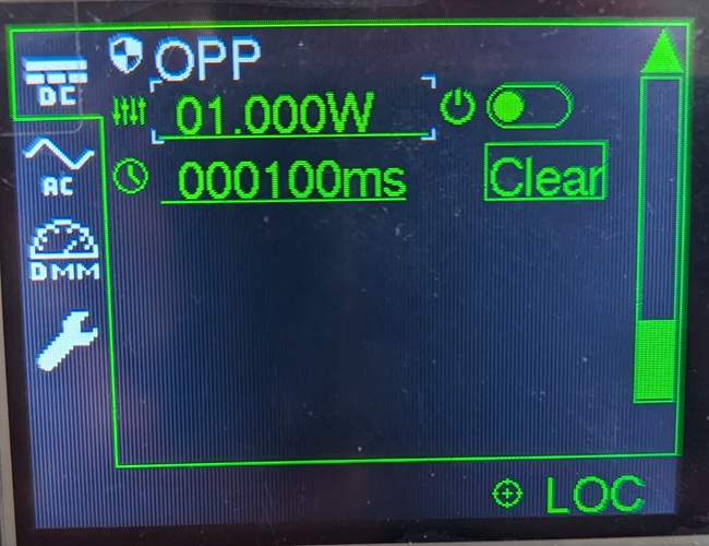
Settings for the over power protection of the power supply channel (protection level in W, Enabled/Disabled state, protection delay after which the protection kicks in, button to clear an active protection)
User interface part for the direct digital synthesis channels of the device.
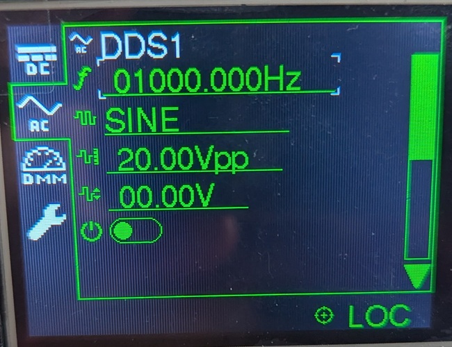
This screen can be used to change the DDS parameters of channel 1 (frequency, waveform type, amplitude, offset, output enabled state).
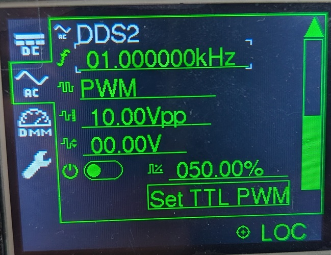
This screen can be used to change the DDS parameters of channel 2 (frequency, waveform type, amplitude, offset, output enabled state).
User interface part for the measurement channels of the device.
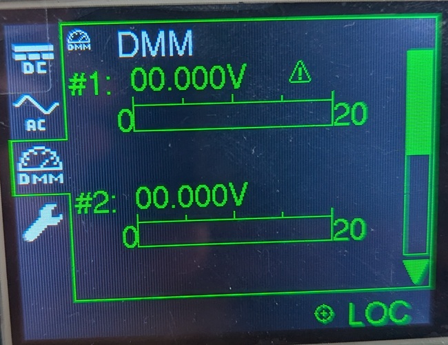
Show the measurements of both digital multimeter channels (DMM1 & DMM2) as value and as bar graph.
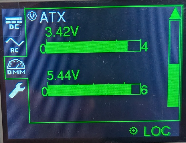
Show the measurements of the +5V and +3.3V ATX voltages as values and as bar graphs.
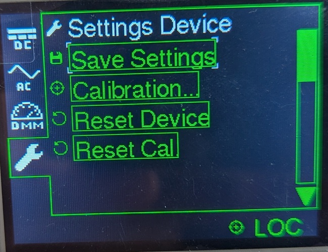
User interface part for different settings of the device.
This screen can be used to save all settings immediatelly (beside the automatic periodical saving), reset all settings, reset the calibration and to start the calibration (guided calibration for all output and input channels).
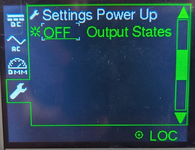
Settings for the output states on power up. The ouputs can always be switched off or on on power up. Also the last output states can be restored on power up.
Screen that shows the same version informations as the welcome screen (developer, serial number of the device, software version number).